Esp8266 (rice) Cooking Machine
Intro
Adding an ESP8266 to a rice cooking machine enables it to become an IoT, and enables me to have rice cooked exactly at the desired time.
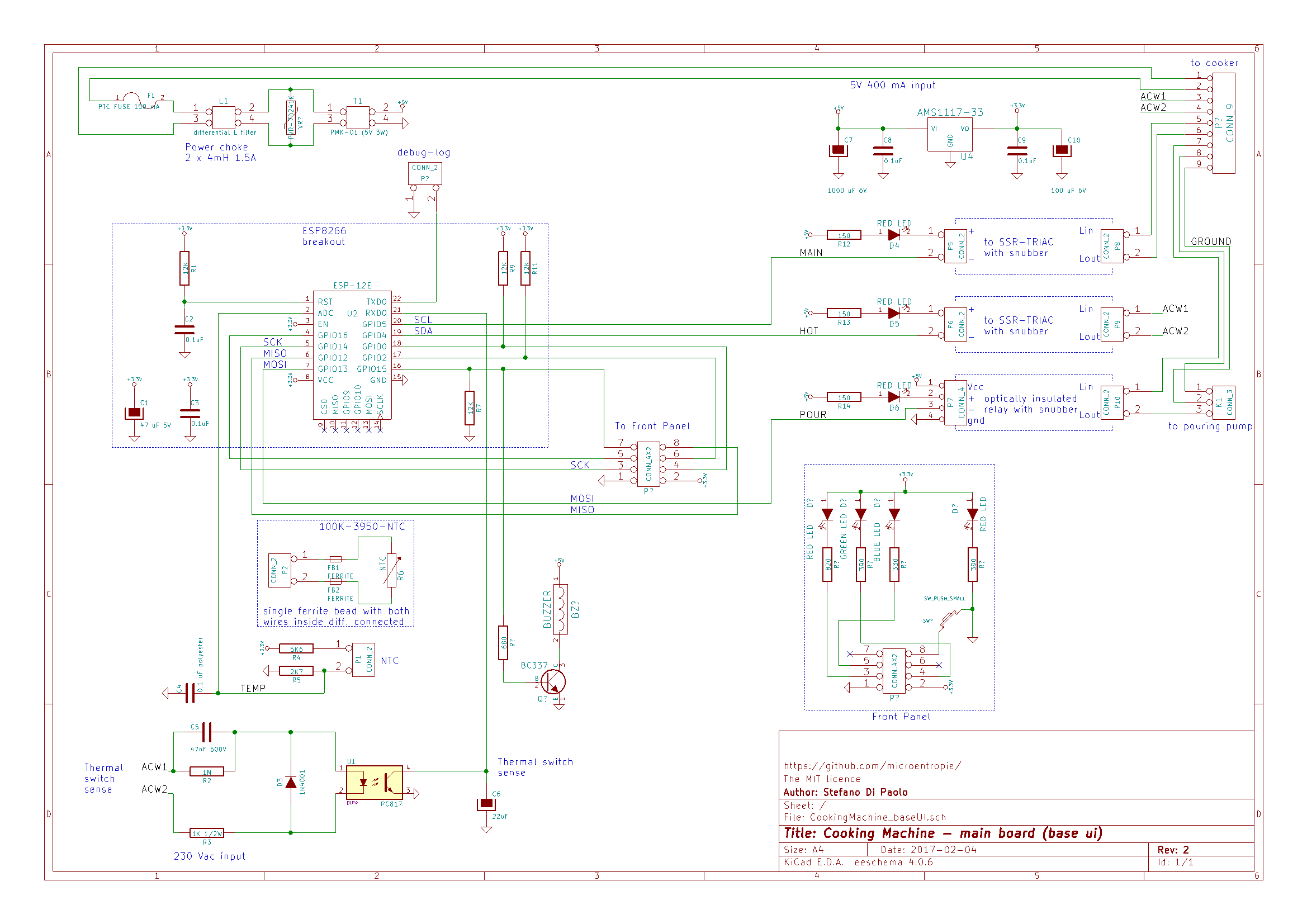
Schematic and full source code is provided at my Github repository:
https://github.com/microentropie/
In the (hope near) future will add a pump to automatically pour water and a programmable ‘taste curve’. See below in ‘Future enhancements’.
DISCLAIMER
- This post describes a circuit that has some parts directly connected to mains voltage. This means risk of injury or even death (electrocution) if not correctly handled. In case you make one, pay attention and avoid touching any live contact with any part of the body. In case of doubt avoid building it.
- Some other parts reach high temperatures (up to 200 °C / 400 °F) thus again attention must be paid: temperature may cause injuries.
- This machine can connect to the internet; like other IOT devices it can not be considered safe, from an intruder point of view, even if some precautions have been taken (see below in the sw section). For this reason it is strongly recommended, as a minimum precaution, to protect it using a good firewall.
Description
Thanks to ESP8266, and its very low price, the machine exposes a web server, can be remotely programmed (firmware update) and configured via some web pages. Configuration does NOT require firmware compilation and update. All parameters are stored in EEPROM and configured by web pages.
The same chip controls both the machine cooking cycle and the web interface. Html pages make (a simple) use of Javascript.
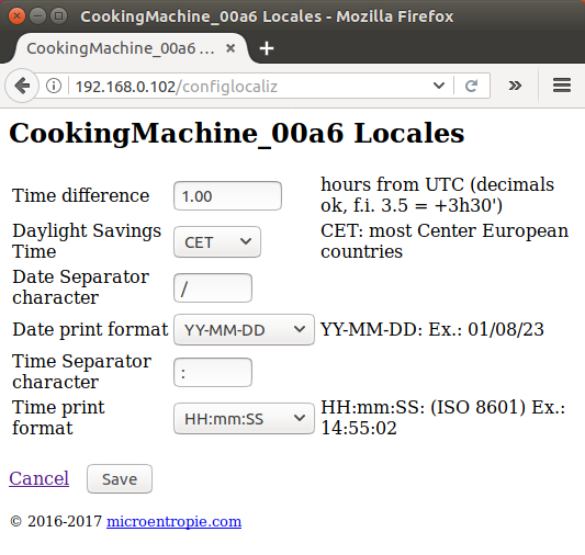
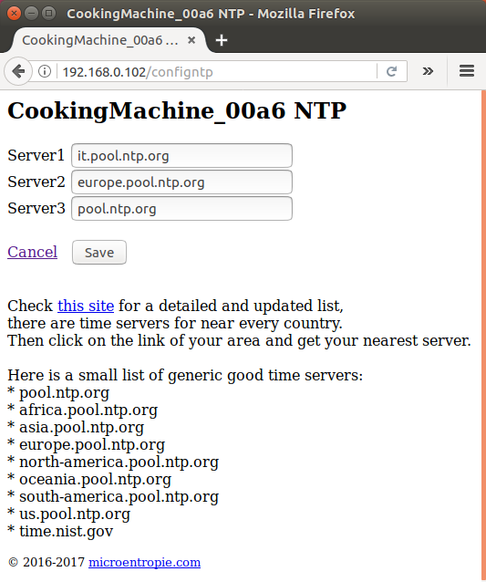
As there is enough flash & eeprom space, the machine gets the time from internet (ntp), manages timezone and DST (daylight savings time).
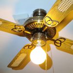
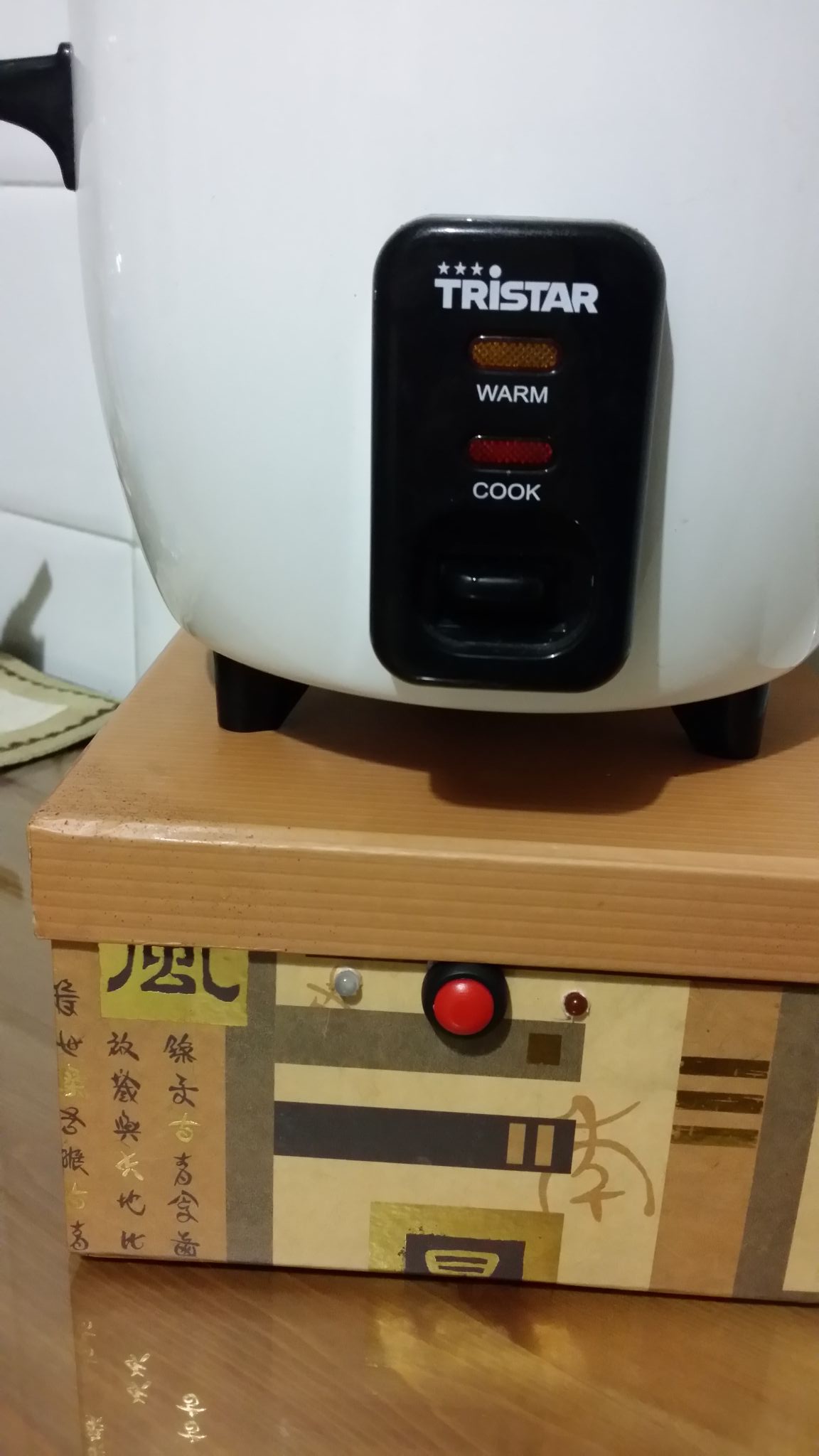
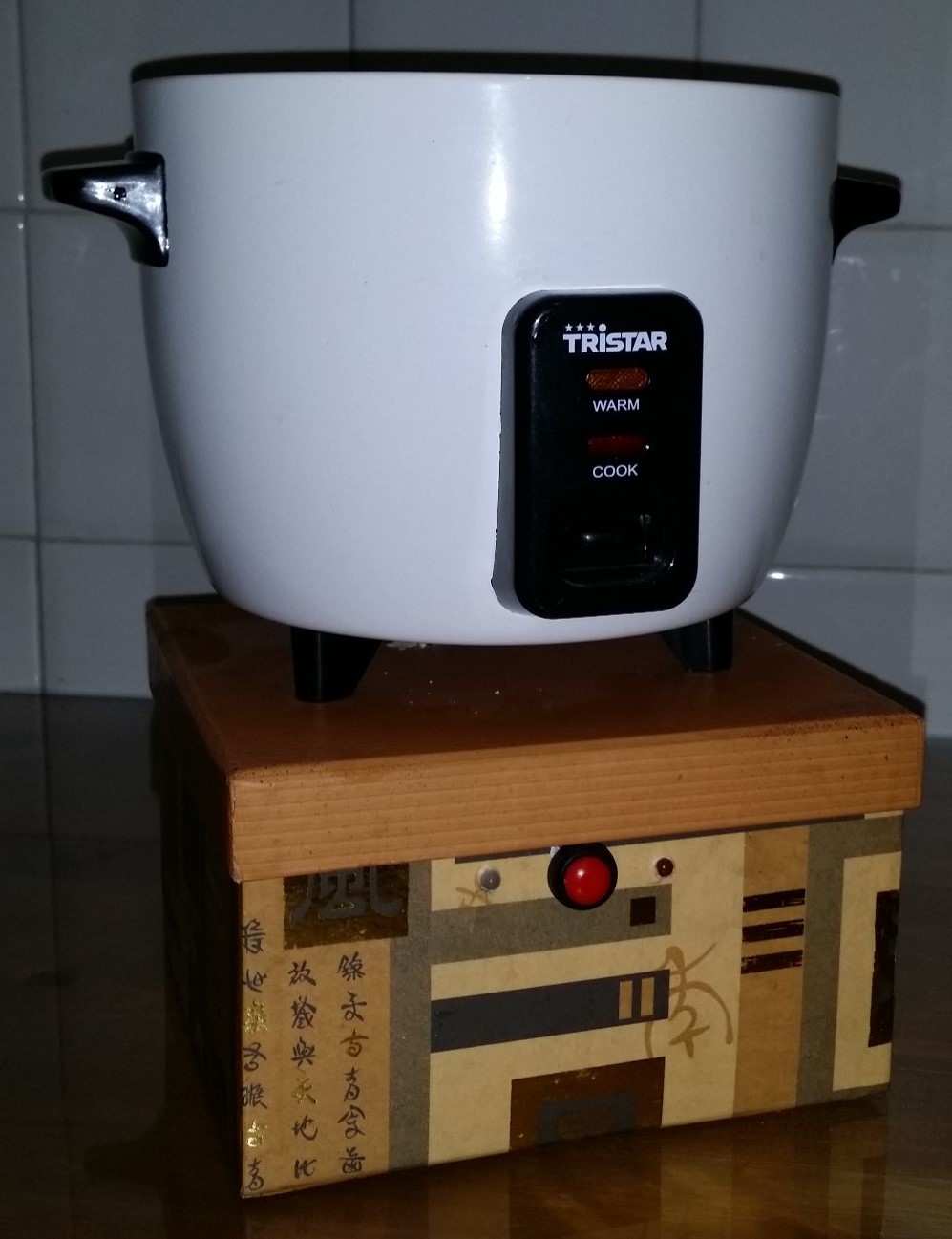
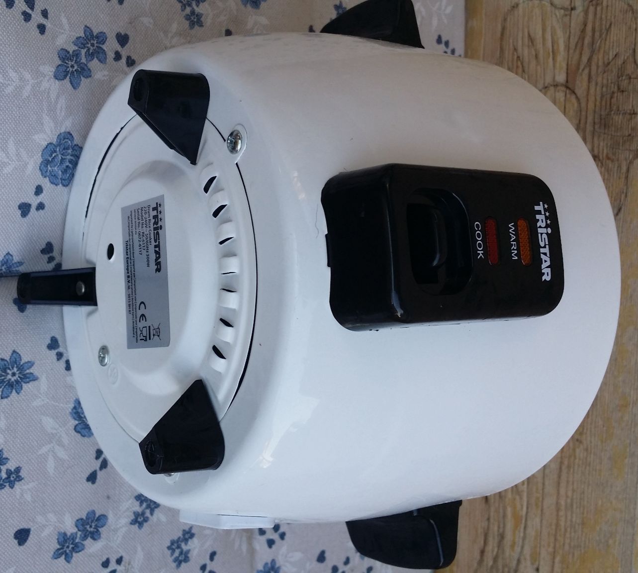
Rice Cooker
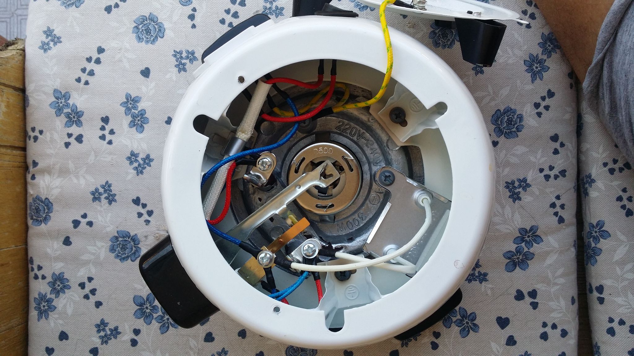
A rice cooking machine costs no more than 30 € and is a quite simple electric device: 2 heating elements (power cooking resistor and ‘keep-warm’ resistor), a main switch, 1 safe/cooking thermal switch, 1 fuse and a couple of lights).
The safe/cooking switch must be manually reset by user and toggles when rice is cooked; a safety thermal fuse protects the whole machine in case something goes wrong and temperature inside the machine rises above a safe limit (194 °C = 391°F).
The key of this machine is the safe/cooking thermal switch that stops heating when temperature rises above 100 °C (212 °F) i.e. when all water evaporated.
A fundamental point is that here, any kind of temperature control is not only useless but detrimental. A constant power level must be applied: water itself guarantees the temperature to be at the constant boiling water value (100 °C), and a small temperature rise (100 to abt 104 °C) is detected by the safe/cooking switch to stop cycle.
Cooking cycle and schematic
Although simple, the rice cooking machine needs to get rice to a completely dry status, thus a layer of rice always sticks to the pot (and it’s not really easy to be removed).
I like rice but not totally dried, so the best solution would be, once cooked, to enter the time machine and go back in time for just a couple of minutes. Not really simple :-), unfortunately I don’t own a Time Machine. That’s why I started this ‘adventure’ some months ago.
How can it be determined when rice is cooked and ready to be served ?
The best solution I found is to check for steam. After an initial warming-up time, steam starts exiting by the lid. When steam flux is nearly over, rice is nearly cooked, approximately 3-5 minutes later the cooking/safe switch will toggle-off cooking. Unfortunately detecting the steam flux is not easy to be implemented and not reliable; along with steam some starch is emitted, detection must deal with temperature, must be easily removable, must be washed after each use.
That’s why I ended up by simply measuring the cooking time.
Here are the requirements for my cooking cycle:
- the safe/cooking switch status must be detected (all the machine safeties must be retained) and all of its original functionalities must be retained
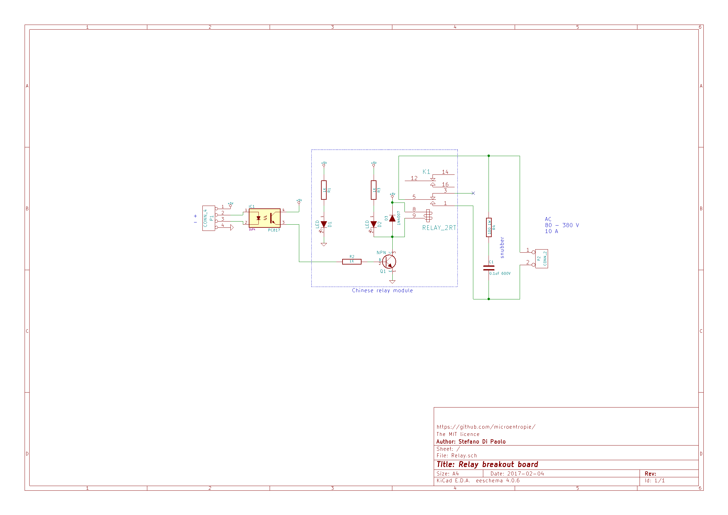
- must be able to work with both relays and SSRs (initially I only had relays, SSRs allow wider programming capabilities)
- must be easily programmed from the web
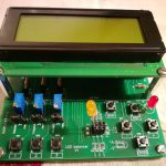
- must retain the possibility to be manually operated ‘by hand’ (start and stop cooking); a minimal interface has 1 button and one LED.
- temperature monitoring is not a big concern but may be useful
I initially provided (later removed) a temperature sensor and for the above explained reason it is here only for pleasure.
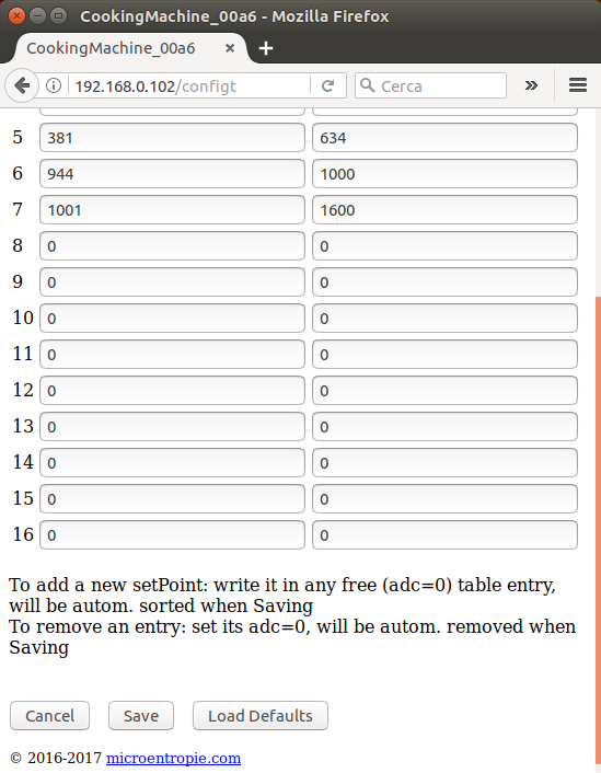
It uses the ESP8266 built-in ADC and a glass type 100K-3950-NTC (cheap 3D printer replacement part). Voltage is reduced by a simple R partition. For several different reasons (resistive partitor configured differently from standard, NTC and R tolerances) I decided to use a set-point table with linear-interpolated measures. This gives the possibility to change NTC type or express temperature in any desired measuring unit without the need to make any further computation. Unfortunately, as the NTC wire is directly (mechanically) coupled to the machine inside, I found it to be a big antenna, bringing all of the AC spurious noise directly to the ESP. The result was instability. Tried a filter, but did not solved all the problems. Only after removing the wire, all the issues have been solved and the machine now works like a charm. I did not deleted the temperature handling from the sw. Maybe in the future will be using a different approach (PT100 or thermocouple).
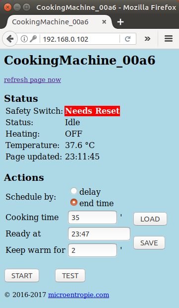
The safe/cooking switch is important so I decided not to hack it in any way. The down side of this is that one must remember to manually reset it or the rice won’t be cooked. This is the main concern because I always load rice + water but (near) always forget to reset it. This means no rice cooked, no food 🙁 and there’s nothing to be done from remote about this.
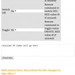
So when the machine is programmed or manually started, it checks for the safe/cooking switch and an alarm (red status on the web page and machine beeps) is sent if not reset. This check involves turning-on heating for a minimum amount of time (0.1 seconds) from time to time.
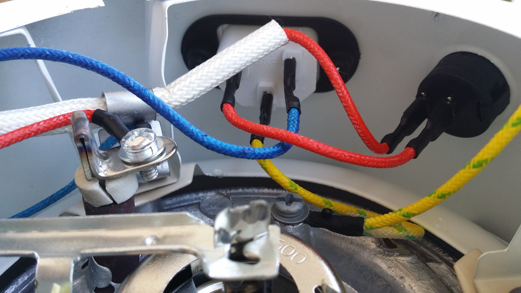
To read status I tried both an AC current sensor and an AC voltage sensor (behind the safe switch contacts). The first does not require ‘tampering’ the machine, the second involves bringing out some wires (using silicon heat resistant wires) from it. So I went for the second solution because I like to open, study and hack devices. Please note I decided not to alter the safe/cooking switch in any way, and as it works at high temperatures it is not safe to insert any kind of mechanical/optical switch in parallel to it.
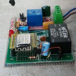
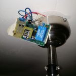
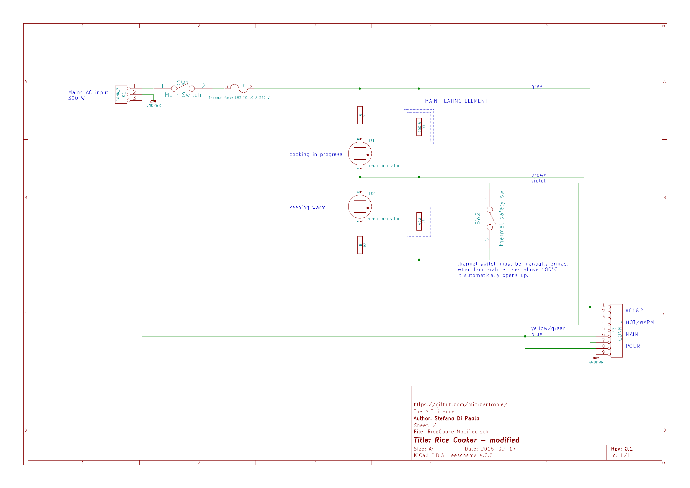
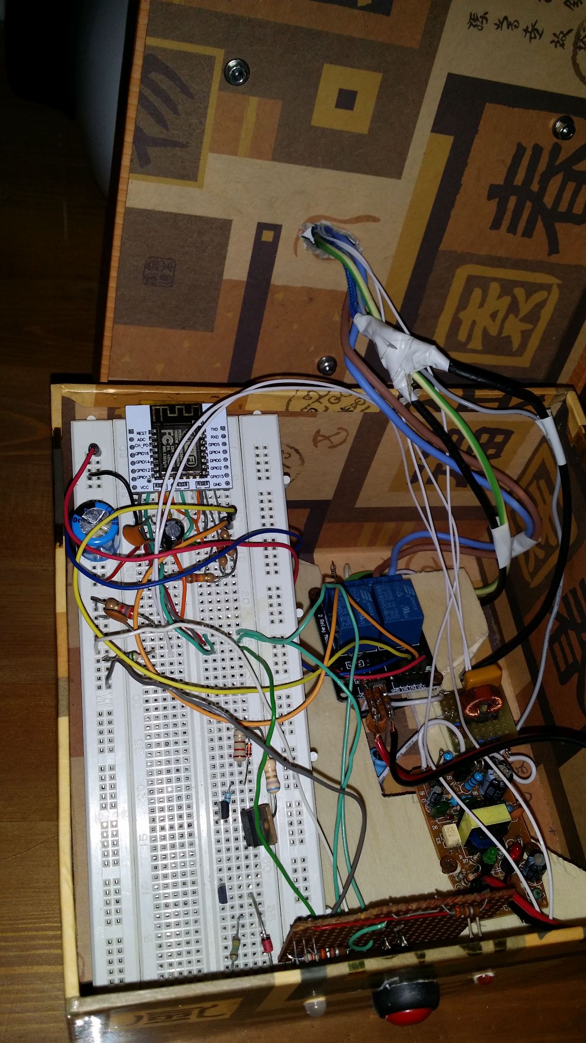
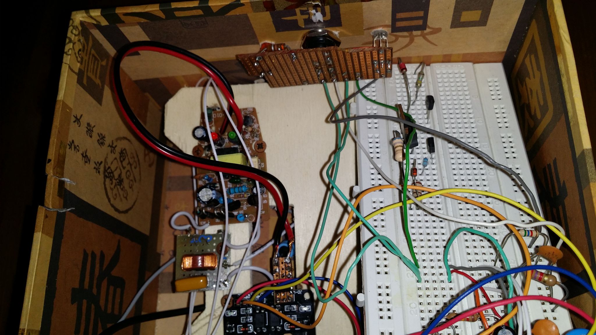
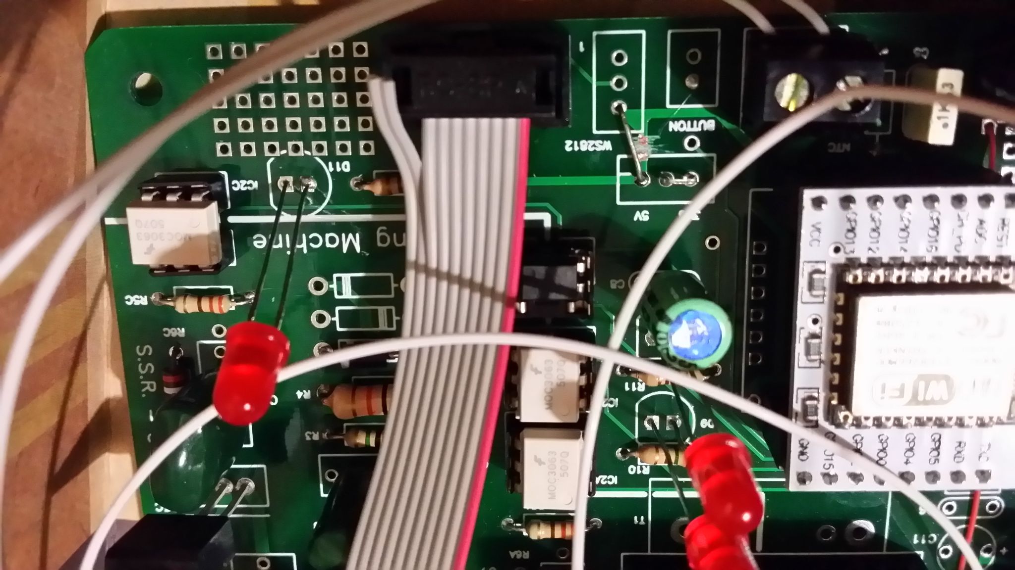
Circuit uses 2 power outputs: 1 main on/off relay, 1 hot/warm relay, and 1 input: the safe/cooking switch detector. A further output is for water pouring (reserved for future uses, see below).
Raw working is easy:
- cooking: both relays on
- keep-warm: main relay ON, hot/warm relay OFF
- off: both relays OFF
safe/cooking switch status detection requires relays to be in the keep-warm status for at least 0.1”.
If for any reason the switch was not reset, cooking will not take place and the machine is ‘electrically’ forced to the keep-warm status (hot/warm relay is series connected to the switch).
Making use or SSRs instead or relays gives a wider range of possibilities like regulating the power, a useful feature with bigger machines when under rice-loaded. Will be handled in a future release.
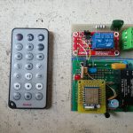
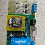
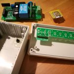
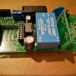
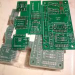
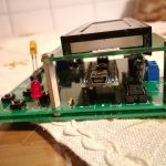
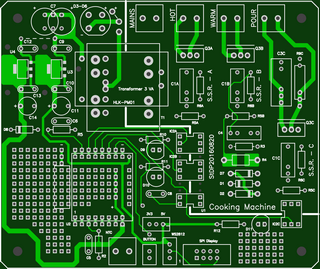
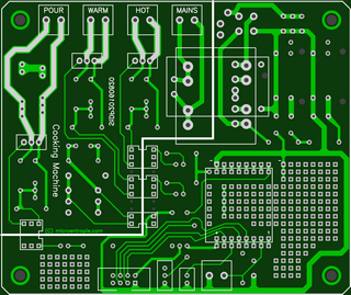
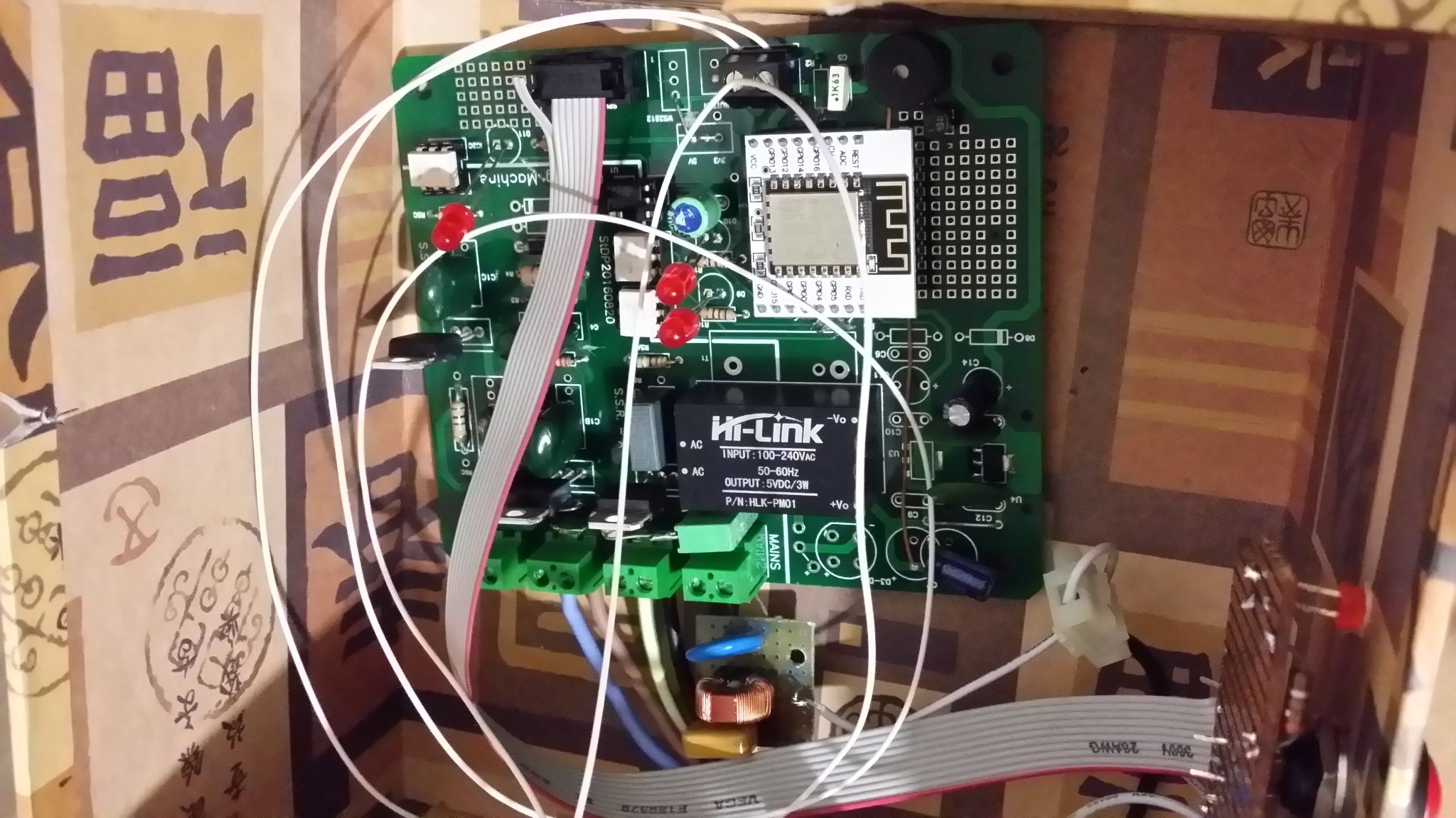
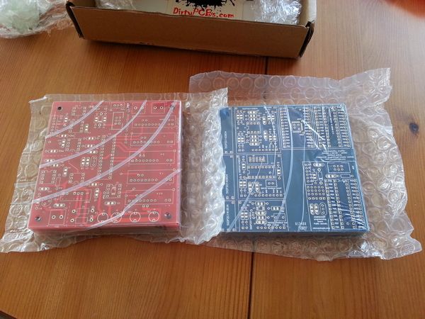
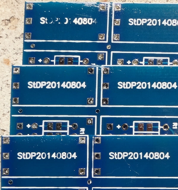
Schematic has been designed with Kicad and a PCB has been printed via EasyEda of which I’m very satisfied. The PCB is not available because I really made a lot of mistakes in design and I don’t plan to make a new one in a short time.
The whole circuit can be easily assembled using readily available components and breakout boards. The only part to be assembled is the safe switch sensor and the front panel.
Components connected to AC are for 230 V 50 Hz mains. Converting to 110V 60 Hz require some changes, I may report a note to the schematic if needed, but wont be able to test.
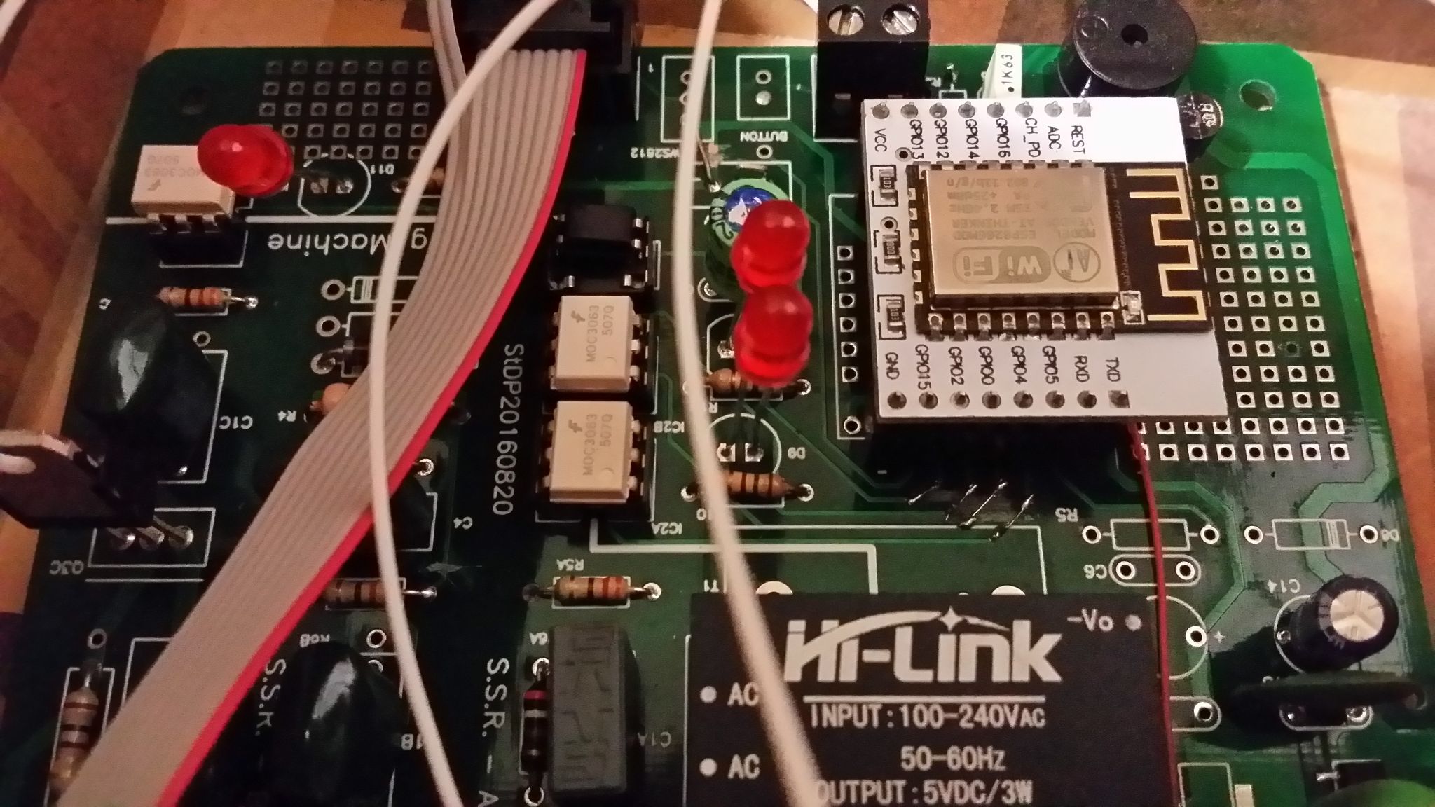
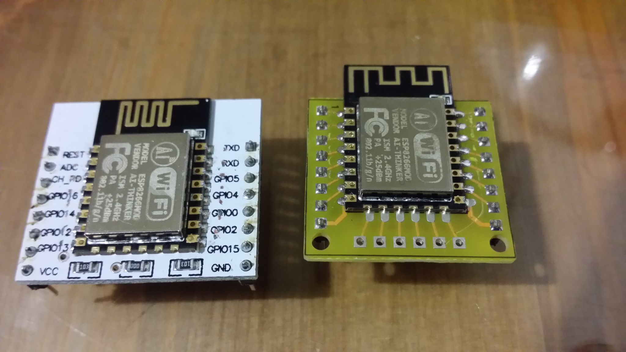
I used a self designed breakout board for ESP8266. It is smaller than the Chinese ones (leaves more space on the breadboard) the top is reserved to ESP12x module and the bottom has all the boot required pull-up and pull-down resistors, a power supply filtering capacitor, a reset circuit and the possibility to directly connect GPIO16 to reset, for deep-sleep mode. Maybe will make a post about it.
The software
Has been built under Arduino (ESP8266 board), currently 1.8.2, but most of the code is reusable under any hw architecture by changing only a few routines; software is organized by layers and libraries.
Portions can be easily reused for other purpopses (example: esp8266 startup and login).
This project has become a reality only thanks to the community and software already written (Arduino Esp8266, …). A special thanks to esp8266.com site for the Arduino port and all the guys that share precious libraries.
A brief description:
- There’s an hw layer (machine_io class) that has to deal with the micro and i/os (example: to get temperature just call the function; it will be retrieved whaterver sensor is used), it has no awareness of what ios are used for.
- An interface layer (machine_if class) where i/os are managed adding some general functionalities, propedeutic for the machine.
- the machine cycle class
- the web-server interface
- libraries for time handling, serialization, sort
- the only exception to this layer oriented approach is related to interrupts: when needed, the implementation tries to reduce the code overhead.
Software could have been written differently and better, but I tried to write code in order to get the highest number of reusable independent blocks.
Some refactoring is needed but unfortunately now haven’t the time for doing that.
Some classes manage time operations (add / subtract / print time and date), time zone and DST.
I don’t like how C standard libraries handle time/date, furthermore ESP8266 has some (linking) problems about this, Arduino does not (nearly) handle this at all. I needed a simple but more flexible way to manage time and date, that’s why I created those DateTimeManipulation classes and functions.
The web interface application allows configuring time zone, DST criteria, how time and date are printed. Settings are serialized (saved) in EEPROM and retrieved at boot time.
This project requires the following Arduino libraries:
| Sort |
Sort an array of objects (any type), by providing the proper sorting function. |
| serializeEeprom |
Read from /write to eeprom any struct/class |
| DateTimeManipulation |
Input and output time and date. Add subtract time … |
About safety against sw hacks, there’s little to be sayed. Like other IOT exposed to the web this machine is not safe. I used some precautions (password protected login, some features like firmware update and configuration are only locally available) but it must be strongly noted that it cannot be considered safe, so using a Proxy is really strongly recommended before exposing the rice cooker to the internet.
Future enhancements
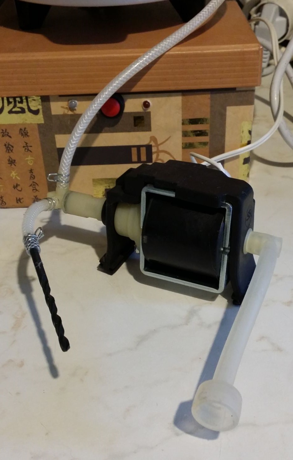
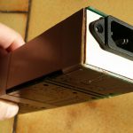
- Remote water loading: this will allow for a real free programming and free cereal usage. Leaving rice (or spelt or any other cereal) in water for some hours is only recommended for some (integral) types. I reserved a specific output to be connected to a SSR for a water pump. Currently experimenting with it, found that a mechanical relay is the best option instead of SSR due to the pure-inductive nature of the load. Pump is from an old espresso machine:
-
- Add a simple ‘taste curve’, required to have quality rice. Example:
- 15 minutes in cold water
- 10 minutes pre-heat (low power) [warm]
- 15 minutes cooking (boiling water) [hot]
- 5 minutes cooling [warm]
- Power partialization (50% or 100% is enough) by pwm, useful when cooking a single small rice portion with big (700 W) machines, requires SSRs.
- Use of SPIFFS file system for data logging (useful for debug).
- Use of SPIFFS file system for blackout recovery (periodical save of current machine state and attempt to recover operation).
- Use of EEPROM (SPIFFS file system) for web interface messages translation.
- Temperature sensor type change. °F/°C web configurable option (temperature is read-in by NTC and setting the measuring unit is simply done by writing the correct set-points).
- A display. With low priority. I made some tests with a small SH1106 SPI OLED display and found that this kind of interface requires a lot of resources and what can be displayed is not really very useful: when behind the machine the cycle status can be instantly checked by a simple look inside the (transparent glass) lid. Temperature is non relevant (steam gives by far the best indication about the cooking status).
- Encoder with button for user input as a complement for the display.
- Upgrade to ESP32. Already got one Expressif Esp32-DEVKITC Core Board V2 (with ESP-WROOM-32).
Not to be implemented
- WS2812. As a minimal display I’m currently using an RGB LED (common-Anode, 4 pins), it’s by far easier to be handled. Made some tests with WS2812, but discarded because it requires a good 3 to 5V line converter and uses a lot of CPU resources. Now I’m happy with just 1 led and 3 resistors; a state change is a single output to a register without timing constraints.
A look at it
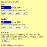
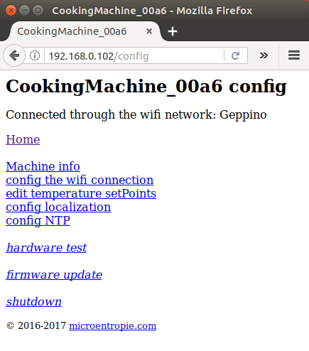
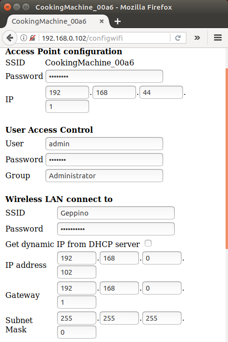
At boot time the machine tries connecting to the WiFi network (if configured and available). If this fails (or if the user switches-on the unit while keeping the button pressed) it creates an Access Point (default IP 192.168.44.1, default password 12345678, everything can be later configured).
In order to access the machine web interface, username (default: admin) and password (default: esp8266) are required.
So the very first time addresses are as follows:
http://192.168.44.1/config goes to the configuration page.
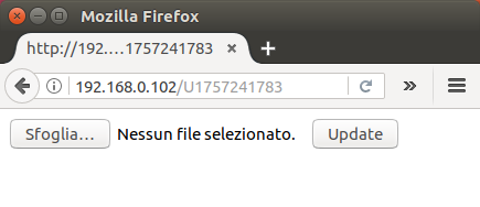
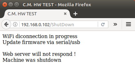
http://192.168.44.1/update goes to the firmware update page. In order to maintain a consistent safety level I needed to use a trick and generate a dynamic URL [*]
http://192.168.44.1/ goes to the normal operation interface. This is the only page allowed by a remote user (source IP address different from 192…).
If configured to receive a dynamic IP by DHCP, the new IP can be retrieved by the serial port monitor. Not really handy, I suggest configuring a static IP.
The 3-colors LED works as follows:
blue-blinking (50% duty cycle) connection attempt to the WiFi network in progress
blue-blinking (1/3 duty cycle) connected to the WiFi network
blue-blinking (2/3 duty cycle) available as a WiFi Access Point
blue-blinking (any duty cycle) good health state indicator
green: cooking completed
red: cooking in progress or programmed.
[*] the ESP8266 firmware update library (ESP8266HTTPUpdateServer class) does not allow for URL filtering, thus any user connecting to the correct page (/update) may be able to upgrade firmware.
I solved this issue by generating a random page URL. The local user connecting to /update page will be redirected to the ‘random’ update page. The internet user will need to guess the correct URL (may require 2^32 attempts) the /update page is not allowed to him. A ‘random’ URL is generated at boot time immediately after firmware update, so when the browser attempts to reconnect to the old ‘random’ page will receive a “404 Not found“ error. The response from the machine web server indicates the machine is again on-line, but simply the url has changed since then. Just type “/update” or “/” or any other valid page.
CREDITS
Arduino
http://www.esp8266.com/
Pcb printed via EasyEda; the on line check and pcb preview is really very handy.
Images processed by Facepixelizer